HiPi::Interface::Seesaw
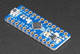
This module provides an interface to the Adafruit ATSAMD09 breakout board as shipped with the default seesaw firmware.
 |
It uses HiPi::Device::I2C as a backend.
IMPORTANT : Boards shipped before 6 October 2020 do not support PWM frequency settings.
See updating firmwareExamples
Methods
- new
- adc_read
- eeprom_read
- eeprom_write
- get_i2c_address
- set_i2c_address
- gpio_get_pin_value
- gpio_set_pin_value
- gpio_set_pin_mode
- gpio_enable_interrupt
- gpio_disable_interrupt
- gpio_get_interrupt_flags
- set_neopixel
- neopixel_set_pixel
- neopixel_set_brightness
- neopixel_show
- neopixel_clear
- pwm_set_frequency
- pwm_set_pulse_width
- pwm_set_duty_cycle
- pwm_can_set_frequency
- pwm_get_frequency
- pwm_get_micros_per_cycle
- read_register
- write_register
- software_reset
- get_date_code
- get_hardware_id
- get_option_names
- get_options
- get_product_code
- get_pwm_width
- get_version
Create a new instance
use HiPi qw( :seesaw );
use HiPi::Interface::Seesaw;

# all params to constructor are optional
# default values are:

my $board = HiPi::Interface::Seesaw->new(
    address      => 0x49,
    devicename   => '/dev/i2c-1',
    reset        => 0,
    action_delay => 500,
);
Constructor arguments
- address - the i2c address of the board. (default 0x49)
- devicename - the i2c device ( default '/dev/i2c-1')
- reset - 0 or 1 - call software_reset on the board. ( default 0 )
- action_delay - microsecond delay interval for common actions ( default 500 )
Read the value of an ADC pin. Returns a 10 bit value between 0 and 1023.
ADC pins are 2,3 and 4 or you may use the constants ( via use HiPi qw( :seesaw ); )
- SEESAW_PA02
- SEESAW_PA03
- SEESAW_PA04
my $value = $board->adc_read( SEESAW_PA02 );
my $volts = $value / 1023 * 3.3;
my $perc  = ($value * 100) / 1023;
Read $numbytes from the EEPROM starting at $address. There are 63 bytes available at addresses 0x00 to 0x3E
If any EEPROM byte has never had a value written, this method will return 0xFF ( 255 ) for that byte
In an array context returns an array of bytes. In a scalar context, returns the first byte retrieved.
my $value = $board->eeprom_read( 0x2A, 1 );
my @values = $board->eeprom_read( 0x2A, 4 );
Write one or more bytes to EEPROM begining at the given address. The optional I2C override address is stored at 0x3F so if your $address @bytes combination would overwrite this, the method will fail.
The method returns the number of bytes written
my $byteswritten = $board->eeprom_write(0x00, @bytes);
It is possible to set an alternative I2C address for the board. This method returns that value.
If no alternative address has been written to EEPROM, the method will return 0xFF ( 255 ).
my $i2c_address = $board->get_i2c_address();
You may set an alternative I2C address for the board if you can't use the default available addresses.
By default the board uses I2C address 0x49 which may be incremented using the AD0 and AD1 pins ( 16 and 17 ) by 1, 2 or 3 to 0x4A, 0x4B or 0x4C.
The increments defined by the state of these address pins are still applied to the address you set.
Therefore if you set an address using this method of 0x30 and the address pins indicate an increment of 2, then on restart the board will listed on address 0x32.
Be sure to set a valid address ( something between 0x08 and 0x77 ).
$board->set_i2c_address( 0x3A );
$board->software_reset;
# change to new address
$board->device->select_address( 0x3A );
Returns the value for one or more gpio pins.
The gpio pins are 9, 10, 11, 14, 15, 24, and 25.
The method returns a scaler value for the first (or only) pin requested if called in a scalar context
It returns an array of values if called in an array context. The values are returned in the order of the pins requested.
my $level = $board->gpio_get_pin_value( 10 );
my @pins = ( 11,15,14,25,9 );
my @levels = $board->gpio_get_pin_value( @pins );

for ( my $i = 0; $i < @pins; $i++ ) {
    print qq(Pin $pins[$i] level = $levels[$i]\n);
}
Set the value for 1 or more pins. Value can be 0 or 1.
Valid gpio pins are 9, 10, 11, 14, 15, 24, and 25.
my $value = 1;
$board->gpio_set_pin_value( 25, 10, 15, $value);

# set single pin low
$board->gpio_set_pin_value( 9, 0);
Set the mode for 1 or more gpio pins.
Mode constants available via use HiPi qw( :seesaw ); are
- SEESAW_INPUT
- SEESAW_OUTPUT
- SEESAW_INPUT_PULLUP
- SEESAW_INPUT_PULLDOWN
$board->gpio_set_pin_mode( 9,10,15, SEESAW_OUTPUT);
$board->gpio_set_pin_mode( 11, SEESAW_INPUT_PULLUP);
Enable interrupts on 1 or more gpio pins.
$board->gpio_enable_interrupt(9,11,15);
Disable interrupts on 1 or more gpio pins.
$board->gpio_disable_interrupt(9,11,15);
Get the interrupt flags for 1 or more pins.
The method returns a scaler value for the first (or only) pin requested if called in a scalar context
It returns an array of values if called in an array context. The values are returned in the order of the pins requested.
my $flag = $board->gpio_get_interrupt_flags( 10 );
my @pins = ( 11,15,14,25,9 );
my @flags = $board->gpio_get_interrupt_flags( @pins );

for ( my $i = 0; $i < @pins; $i++ ) {
    print qq(Pin $pins[$i] interrupt flag = $flags[$i]\n);
}
You can use one gpio pin to drive neopixels. The method sets the parameters for the pin and pixel type.
# Parameters and their defaults
use HiPi qw( :seesaw );

.......

$board->set_neopixel(
    pin        => 10,                     # pin number ( required, no default )
    pixels     => 8,                      # number of pixels ( required, no default )
    colourmap  => SEESAW_NEOPIXEL_GRBW,   # type of pixels
    speed      => SEESAW_NEOPIXEL_KHZ800, # speed
    brightness => 5,                      # default brightness
);
colourmap is the type of pixel. One of
- SEESAW_NEOPIXEL_GRBW
- SEESAW_NEOPIXEL_RGBW
- SEESAW_NEOPIXEL_GRB
- SEESAW_NEOPIXEL_RGB
speed. One of
- SEESAW_NEOPIXEL_KHZ800
- SEESAW_NEOPIXEL_KHZ400
brightness - this is the default brightness for pixels. A value between 1 and 100.
Set the red, green, blue, white and brightness for the numbered pixel.
For RGB / GRB pixels ( no white ) the value of $w is ignored.
Defining brightness is optional. If nothing is defined then the default brightness passed in the constructor or by neopixel_set_brightness() is used.
# examples will work for RGB, GRB, RGBW and GRBW pixels
# use 10 as optional pixel brightness
my @red         = ( 255,   0,   0,   0,  10 );
my @green       = (   0, 255,   0,   0,  10 );
my @blue        = (   0,   0, 255,   0,  10 );
my @yellow      = ( 255, 255,   0,   0,  10 );
my @cyan        = (   0, 255, 255,   0,  10 );
my @magenta     = ( 255,   0, 255,   0,  10 );
my @orange      = ( 255,  40,   0,   0,  10 );
my @white       = ( 255, 255, 255, 255,  10 );

$board->neopixel_set_pixel( 0, @red );
$board->neopixel_set_pixel( 1, @green );
$board->neopixel_set_pixel( 2, @blue );
$board->neopixel_set_pixel( 3, @yellow );
$board->neopixel_set_pixel( 4, @cyan );
$board->neopixel_set_pixel( 5, @magenta );
$board->neopixel_set_pixel( 6, @orange );
$board->neopixel_set_pixel( 7, @white );

$board->neopixel_show();
Set default brightness for pixels to be used when no brightness is specified in neopixel_set_pixel.
A number between 0 and 100
$board->neopixel_set_brightness( 20 );
The values set in neopixel_set_pixel() are buffered until you call neopixel_show.
$board->neopixel_show();
Sets all pixels off
$board->neopixel_clear();
Boards shipped from Adafruit after 6 October 2020 allow you to set the PWM frequency. If you have a board shipped before this, it is possible to update the firmware if you have the necessary tools. See updating firmware
The method returns the true frequency set.
# set 50Hz frequency for pin 5

my $truefrequency = $board->pwm_set_frequency(5, 50);

# $truefrequency for 50 == 45.0727925599844
The ATSAMD09 and firmware sets PWM frequency using clock dividers. Passing a frequency in Hz to the method causes firmware to choose a clock divider as follows:
if( freq > 500) prescale = TC_CTRLA_PRESCALER_DIV1_Val;             = 720Hz
else if( freq > 250 ) prescale = TC_CTRLA_PRESCALER_DIV2_Val;       = 360Hz
else if( freq > 140 ) prescale = TC_CTRLA_PRESCALER_DIV4_Val;       = 180Hz
else if( freq > 75 ) prescale = TC_CTRLA_PRESCALER_DIV8_Val;        = 90Hz
else if( freq > 25 ) prescale = TC_CTRLA_PRESCALER_DIV16_Val;       = 45Hz
else if( freq > 7 ) prescale = TC_CTRLA_PRESCALER_DIV64_Val;        = 11.25Hz
else prescale = TC_CTRLA_PRESCALER_DIV256_Val;                      = 2.8125Hz
The method calculates the true value to return as:
$returnval = 48000000 / ( $divider * ( 65535 + 1024 ) );
Available PWM pins are 5, 6 and 7
Note that timers on the ATSAMD09 are shared between pins. Any value set for pin 6 or 7 will affect both pins. Values set for pin 5 do not affect other pins in the standard firmware.
Set the width of a pulse on a pin in microseconds.
my $dutycycle = $board->pwm_set_pulse_width( 5, 1000)
The method calls pwm_set_duty_cycle() with the correct value to produce the desired pulse width. The method returns the duty cycle used
Set the extent of the cycle for which the pin will be high as a number between 0 and 65535 ( 65535 == 100% );
my $cycle = $board->pwm_set_duty_cycle(5, 2954);
As the module records the true freqency set when pwm_set_frequency() is called, the pwm_set_pulse_width() method is able to calculate the necessary value to pass to pwm_set_duty_cycle() to achieve the desired pulse width.
The method returns true / false to indicate if the firmware on the board can set a frequency.
If it cannot, you will find that the PWM frequency is set at around 2.885 kHz.
my $bool = $board->pwm_can_set_frequency();
Returns the true frequency set for a pin during a previous call to pwm_set_frequency()
If pwm_set_frequency() has not been called since the instance was created or software_reset() was called, this method returns zero.
my $freq = $board->pwm_get_frequency(5);
Returns the microseconds per cycle calculated from the true frequency set during a previous call to pwm_set_frequency()
If pwm_set_frequency() has not been called since the instance was created or software_reset() was called, this method returns zero.
my $us_per_cycle = $board->pwm_get_micros_per_cycle(5);
This is the low level method used to make I2C read requests to the board. You may not need this method if the higher level methods work as you require and expect.
The method returns an array of bytes received from the board.
$numbytes is the number of bytes to read.
$delay is an optional parameter that you may use to override the default delay in read operations of 500 us.
The following constants are available via use HiPi qw( :seesaw )
for $regbase and $regmember if you find direct calls to read_register() that are
useful.
- SEESAW_STATUS_BASE
- SEESAW_STATUS_HW_ID
- SEESAW_STATUS_VERSION
- SEESAW_STATUS_OPTIONS
- SEESAW_STATUS_SWRST
- SEESAW_GPIO_BASE
- SEESAW_GPIO_DIRSET_BULK
- SEESAW_GPIO_DIRCLR_BULK
- SEESAW_GPIO_BULK
- SEESAW_GPIO_BULK_SET
- SEESAW_GPIO_BULK_CLR
- SEESAW_GPIO_BULK_TOGGLE
- SEESAW_GPIO_INTENSET
- SEESAW_GPIO_INTENCLR
- SEESAW_GPIO_INTFLAG
- SEESAW_GPIO_PULLENSET
- SEESAW_GPIO_PULLENCLR
- SEESAW_TIMER_BASE
- SEESAW_TIMER_STATUS
- SEESAW_TIMER_PWM
- SEESAW_TIMER_FREQ
- SEESAW_ADC_BASE
- SEESAW_ADC_STATUS
- SEESAW_ADC_INTEN
- SEESAW_ADC_INTENCLR
- SEESAW_ADC_WINMODE
- SEESAW_ADC_WINTHRESH
- SEESAW_ADC_CHANNEL_OFFSET
- SEESAW_NEOPIXEL_BASE
- SEESAW_NEOPIXEL_STATUS
- SEESAW_NEOPIXEL_PIN
- SEESAW_NEOPIXEL_SPEED
- SEESAW_NEOPIXEL_BUF_LENGTH
- SEESAW_NEOPIXEL_BUF
- SEESAW_NEOPIXEL_SHOW
- SEESAW_EEPROM_BASE
my ( $hardware_id ) = $board->read_register( SEESAW_STATUS_BASE, SEESAW_STATUS_HW_ID, 1 );
This is the low level method used to write bytes over I2C to the board. You may not need this method if the higher level methods work as you require and expect.
See method read_register() for the constants available for $regbase and $regmember.
$board->write_register(SEESAW_STATUS_BASE, SEESAW_STATUS_SWRST, 0xFF);
Resets the board to its power on state.
$board->software_reset();
The board status register contains a version number that contains a product code and a date code. This method returns the date code part.
For example, the original release of the seesaw breakout has a date code of 20171023
The 6 October 2020 release of the seesaw breakout has a date code of 20200831
my $datecode = $board->get_date_code()
The board status register contains a hardware id. For the ATSAMD09 breakout board this is 0x55
Method code example
Translate the value returned by method get_options() into a readable string.
my $namestring = $board->get_options();
The board status register contains a value indicating which options are compiled into the firmware. For the standard firmware shipped on the ATSAMD09 breakout board this is 0x4B03.
The method get_option_names() translates these into a readable string.
my $optioncode = $board->get_options();
The board status register contains a version number that contains a product code and a date code. This method returns the product code part.
The product code for the ATSAMD09 breakout board is 3657.
my $productcode = $board->get_product_code();
Returns 8 or 16 indicating the number of bits available to PWM functions which depends on the version of firmware shipped on the board. Firmware with 8 bit PWM functions does not allow setting the PWM frequency. See updating firmware
my $numbits = $board->get_pwm_width();The board status register contains a version number that contains a product code and a date code. This method returns the version number.
You may find the get_date_code() and get_product_code() methods more useful.
my $version = $board->get_version();
Examples
Board Info
Print information about the board
#!/usr/bin/perl
use strict;
use warnings;
use HiPi qw( :seesaw );
use HiPi::Interface::Seesaw;

# call with seesaw hex address
# e.g. seesaw/info.pl 0x49

my $seesawaddress = ( $ARGV[0] ) ?  hex($ARGV[0]) : 0x49;

my $dev = HiPi::Interface::Seesaw->new(
    address     => $seesawaddress,
);
print qq(------------------------------\n);
print qq(Seesaw Breakout Info\n);
print qq(------------------------------\n);
print 'Version       : ' . $dev->get_version . qq(\n);
print 'Version Date  : ' . $dev->get_date_code . qq(\n);
print 'Product Code  : ' . $dev->get_product_code . qq(\n);
my $pwmwidth = $dev->get_pwm_width;
print 'PWM Width     : ' . $pwmwidth . qq(\n);
my $hid = $dev->get_hardware_id;
printf(qq(Hardware ID   : 0x%X\n), $hid);
my $opts = $dev->get_options;
printf(qq(Options       : 0x%X\n), $opts);
my $i2c = $dev->get_i2c_address();
printf(qq(EEPROM I2C    : 0x%02X\n), $i2c);
my $optionnames = $dev->get_option_names();
print 'OPTION NAMES  : ' . $optionnames . qq(\n);

1;
Neopixel control
Control neopixels from a seesaw gpio pin
#!/usr/bin/perl
use strict;
use warnings;
use HiPi qw( :seesaw );

# call with seesaw hex address
# e.g. seesaw/neopixel.pl 0x49

my $demopin = SEESAW_PA010;
my $demopixels = 8;

package HiPi::Example::Seesaw;
use HiPi qw( :seesaw );
use parent qw( HiPi::Interface::Seesaw );

__PACKAGE__->create_accessors( qw( exit_processed demopin demopixels ) );

sub new {
    my ( $class, %params ) = @_;
    my $self = $class->SUPER::new( %params );
    HiPi->register_exit_method( $self, 'exit');
    return $self;
}

sub exit {
    my $self = shift;
    return if $self->exit_processed;
    print qq(\nExecution ending : cleaning up\n);
    $self->neopixel_clear;
    $self->software_reset;
    $self->exit_processed(1);
    return;
}

sub process {
    my $self = shift;

    print qq(Neopixel demo\n);
    print qq(\nPress CTRL + C to exit\n\n);

    $self->set_neopixel(
        pin    => $self->demopin,
        pixels => $self->demopixels,
    );

    my $max_brightness = 100;  # between 0 and 100

    # colours are always ( Red, Green, Blue, White, Brightness )

    my @red = ( 255, 0, 0,0,5 );
    my @green = ( 0, 255, 0,0,5 );
    my @blue = ( 0, 0, 255,0,5 );
    my @yellow = ( 255, 255, 0,0,5 );
    my @cyan = ( 0, 255, 255,0,5 );
    my @magenta = ( 255, 0, 255,0,5 );
    my @orange = ( 255, 40, 0,0,5 );
    my @white = ( 255, 255, 255,0,5 );
    my @brightwhite = ( 255, 255, 255, 255, 5 );

    my @pixelbuffer = (
        [ 255, 0, 0, 0, 5 ],
        [ 0, 255, 0, 0, 5 ],
        [ 0, 0, 255, 0, 5 ],
        [ 0, 0, 0, 255, 5 ],
        [ 255, 255, 0, 0, 5 ],
        [ 0, 255, 255, 0, 5 ],
        [ 255, 0, 255, 0, 5 ],
        [ 255, 255, 255, 0,5 ],
    );

    $self->neopixel_clear;

    $self->set_all_colour(\@brightwhite );
    $self->sleep_milliseconds(2500);

    $self->do_pixel_buffer(\@pixelbuffer);
    $self->sleep_milliseconds(2500);

    # cycle colours for a bit

    my $stop = time + 5;
    while ( $stop > time ) {
        $self->do_pixel_buffer( \@pixelbuffer);
        unshift( @pixelbuffer, pop( @pixelbuffer) );
        $self->sleep_milliseconds( 150 );
    }

    # set colours and fade in / out

    for my $colour ( \@white, \@red, \@green, \@blue, \@yellow, \@cyan, \@magenta, \@orange ) {
        my @usecolour = @$colour;
        my $brightness = 5;
        while( $brightness < $max_brightness ) {

            $usecolour[-1] = $brightness;
            $self->set_all_colour(\@usecolour );
            $self->sleep_milliseconds(20);
            $brightness += 5;
        }

        while( $brightness >= 0 ) {
            $usecolour[-1] = $brightness;
            $self->set_all_colour(\@usecolour );
            $self->sleep_milliseconds(20);
            $brightness -= 5;
        }
    }
}

sub do_pixel_buffer {
    my ($self, $pixelbuffer) = @_;
    for( my $i = 0; $i < 8; $i++ ) {
        $self->neopixel_set_pixel($i, @{ $pixelbuffer->[$i] } );
    }
    $self->neopixel_show;
}

sub set_all_colour {
    my ($self, $colour) = @_;

    for( my $i = 0; $i < 8; $i++ ) {
        $self->neopixel_set_pixel($i, @$colour );
    }
    $self->neopixel_show;
}

package main;

my $seesawaddress = ( $ARGV[0] ) ?  hex($ARGV[0]) : 0x49;

my $dev = HiPi::Example::Seesaw->new(

    address    => $seesawaddress,
    demopin    => $demopin,
    demopixels => $demopixels,
    reset      => 1,

);

$dev->process;

1;
PWM control
Use a PWM pin to output different pulse widths
#!/usr/bin/perl
use strict;
use warnings;
use HiPi qw( :seesaw );

# call with seesaw hex address
# e.g. seesaw/pwm.pl 0x49

my $pwmpin     = SEESAW_PA05;
my $frequency  = 50;
my $pulsewidths = [ 1000, 1500, 2000 ];

package HiPi::Example::Seesaw;
use HiPi qw( :seesaw );
use parent qw( HiPi::Interface::Seesaw );

__PACKAGE__->create_accessors( qw( exit_processed pwmpin pwmfreq pulsewidths ) );

sub new {
    my ( $class, %params ) = @_;
    my $self = $class->SUPER::new( %params );
    HiPi->register_exit_method( $self, 'exit');
    return $self;
}

sub exit {
    my $self = shift;
    return if $self->exit_processed;
    print qq(\nExecution ending : cleaning up\n);
    $self->software_reset;
    $self->exit_processed(1);
    return;
}

sub process {
    my $self = shift;
    my $width = $self->pulsewidths->[0];
    printf(qq(Setting pin %s with frequency %s and pulse width %s us\n),
           $self->pwmpin, $self->pwmfreq, $width );

    my $realfreq  = $self->pwm_set_frequency($self->pwmpin, $self->pwmfreq );
    my $dutycycle = $self->pwm_set_pulse_width($self->pwmpin, $width );

    print qq(Real frequency produced by selected divider is $realfreq\n);
    print qq(Duty cycle calculated from pulse width $width is $dutycycle / 65535\n);

    print qq(\nPress CTRL + C to exit\n\n);

    STDOUT->autoflush(1); # so print '.' is flushed;

    while ( 1 ) {
        for ( my $i = scalar ( @{ $self->pulsewidths }) -1; $i >= 0; $i -- ) {
            sleep 5;
            $width = $self->pulsewidths->[$i];
            print qq(Setting pulse width to $width us\n);
            $dutycycle = $self->pwm_set_pulse_width($self->pwmpin, $width );
            print qq(Duty cycle is $dutycycle\n);
            print qq(Press CTRL + C to exit\n\n);
        }
    }
}

package main;

my $seesawaddress = ( $ARGV[0] ) ?  hex($ARGV[0]) : 0x49;

my $dev = HiPi::Example::Seesaw->new(

    address     => $seesawaddress,
    reset       => 1,
    pwmpin      => $pwmpin,
    pwmfreq     => $frequency,
    pulsewidths => $pulsewidths,

);

$dev->process;

1;
Interrupts
Handle interrupts
#!/usr/bin/perl
use strict;
use warnings;
use HiPi qw( :rpi :seesaw );

# call with seesaw hex address
# e.g. seesaw/interrupt.pl 0x49

my $pi_int_pin    = RPI_PIN_40;    # input pin on pi connected to seesaw irq pin 8
my $pi_out_pin    = RPI_PIN_38;    # output pin on pi connected to seesaw input pin 11
my $seesaw_in_pin = SEESAW_PA011;  # seesaw input pin - high / low will trigger interrupts

package HiPi::Example::Seesaw;
use HiPi qw( :seesaw :rpi );
use parent qw( HiPi::Interface::Seesaw );
use HiPi::GPIO;

__PACKAGE__->create_accessors( qw( exit_processed pi_int_pin pi_out_pin seesaw_in_pin rasp ) );

sub new {
    my ( $class, %params ) = @_;
    $params{rasp} = HiPi::GPIO->new;
    my $self = $class->SUPER::new( %params );
    HiPi->register_exit_method( $self, 'exit');
    return $self;
}

sub exit {
    my $self = shift;
    return if $self->exit_processed;
    print qq(\nExecution ending : cleaning up\n);
    $self->rasp->set_pin_mode(  $self->pi_int_pin, RPI_MODE_INPUT );
    $self->rasp->set_pin_pud(   $self->pi_int_pin, RPI_PUD_OFF );
    $self->rasp->set_pin_mode(  $self->pi_out_pin, RPI_MODE_INPUT );
    $self->software_reset;
    $self->exit_processed(1);
    return;
}

sub process {
    my $self = shift;

    print qq(Press CTRL + C to end\n);

    my $ppint = $self->pi_int_pin;
    my $ppout = $self->pi_out_pin;
    my $sppin = $self->seesaw_in_pin;

    # setup Raspberry Pins;
    $self->rasp->set_pin_mode(  $ppint, RPI_MODE_INPUT );
    $self->rasp->set_pin_pud(   $ppint, RPI_PUD_UP );
    $self->rasp->set_pin_mode(  $ppout, RPI_MODE_OUTPUT );
    $self->rasp->set_pin_level( $ppout, 0 );

    # setup Seesaw Pins
    $self->gpio_set_pin_mode(  $sppin, SEESAW_INPUT_PULLUP );
    $self->gpio_enable_interrupt( $sppin );
    $self->gpio_get_interrupt_flags( $sppin ); # clears interrupt state for all pins

    # let everything settle
    $self->sleep_microseconds( 1000 );

    my $counter = 0;
    while ( $counter > -1 ) {
        $counter ++;

        my $toggle = $counter % 2;

        # set our value
        $self->rasp->set_pin_level( $ppout, $toggle );

        # poll int pin and wait till interrupt set
        my $interrupt_confirmed = $self->poll_int_pin;

        unless( $interrupt_confirmed ) {
            # this would mean something went badly wrong
            # so exit everything
            warn qq(Interrupt flag for $sppin does not show as set in iteration $counter);
            return;
        }

        # wait for interrupt to be cleared
        # this happens after the IRQ pin on seesaw is
        # no longer pulled low

        while ( $interrupt_confirmed ) {
            ( $interrupt_confirmed ) = $self->gpio_get_interrupt_flags( $sppin );
            $self->sleep_microseconds( 500 );
        }

        unless( $counter % 100 ) {
            print qq($counter iterations completed successfully\n);
            print qq(Press CTRL + C to end\n);
        }
    }
}

sub poll_int_pin {

    # poll the interrupt pin until it is pulled low by interrupt

    my $self = shift;
    my $intpin = $self->pi_int_pin;
    my $sppin = $self->seesaw_in_pin;
    my $level = 1;

    while ( $level ) {
        $self->sleep_microseconds( 500 );
        $level = $self->rasp->get_pin_level( $intpin );
    }

    # this will clear ALL interrupt flags
    my ( $intvalue ) = $self->gpio_get_interrupt_flags( $sppin );
    return $intvalue;
}

package main;

my $seesawaddress = ( $ARGV[0] ) ?  hex($ARGV[0]) : 0x49;

my $dev = HiPi::Example::Seesaw->new(

    address       => $seesawaddress,
    reset         => 1,
    pi_int_pin    => $pi_int_pin,
    pi_out_pin    => $pi_out_pin,
    seesaw_in_pin => $seesaw_in_pin,

);

$dev->process;

1;
Updating Firmware
Adafruit ATSAMD09 breakout board has shipped with 2 versions of firmware installed.
The first version carrying a date code of 20171023 does not allow setting PWM frequency and has a bug when attempting to use more than 63 neopixels.
A later version of firmware fixes these issues and carries a date code of 20200831. It is present on boards shipped after 6 October 2020
Because the ATSAMD09 breakout board by design allows you to reprogram and reconfigure the chip by changing and updating the firmware, it is possible to update boards shipped before 6 October 2020 to the latest firmware however you do need some tools that will allow you to update the firmware.
I have used compilation of the firmware on Ubuntu and installation to the seesaw using
an
Adafruit Feather M0 Adalogger.
This allowed me to upload the compiled firmware to the seesaw board from an SD Card.
To compile the firmware first install the ARM 9-2019-q4-major version tool chain as described at Install Build Tools on Ubuntu.
The latest officially released firmware version at the time of writing is 1.1.6 available from https://github.com/adafruit/seesaw/releases/tag/1.1.6Download the source code with
wget https://github.com/adafruit/seesaw/archive/1.1.6.tar.gz
After extracting you can build following the instructions at
https://github.com/adafruit/seesaw/blob/master/README.md
There is a slight typo with capitalisation there. The make command is:
make BOARD=samd09Breakout
Make sure the ARM gcc binaries are in your path.
Once compilation is complete you will have
build/samd09Breakout/seesaw-samd09Breakout.bin
Copy it to an SD card renaming the file fw.bin.
Follow the instructions at programming-an-m0-using-an-arduino
The instructions are for a Gemma M0 but the process for the SAMD09 Breakout is identical. For reference the pin connections required for the SAMD09 seesaw breakout are:
| Feather MO Adalogger | ATSAMD09 seesaw breakout |
|---|---|
| GND | GND |
| 11 | RST |
| 10 | SWD |
| 9 | SWC |
| 3V3 | VIN |